There is much literature about the use of FPGAs for digital signal processing applications: the ability to run operations in parallel to achieve higher performance, or being able to run real time operations in a pipelined video or imaging system, or for applications which aren’t highly sequential in nature. But having made the decision to use an FPGA for your DSP, can’t it simply be created in HDL and simulation tested using a traditional digital simulator? The answer is yes, however for anything but the simplest of algorithms, one would be better off using Matlab / Simulink for reasons of simulation.

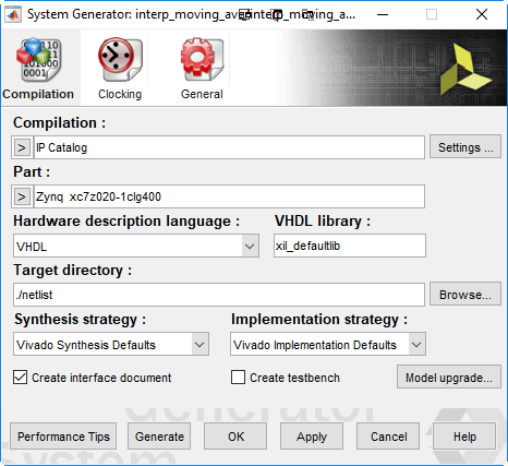
There are a couple of different options for capturing the design in Simulink. One is to use HDL Coder which is a Mathworks add-on tool, and the second is to use Xilinx System Generator for DSP, or as it is now called, Model Composer.

There are a few options when using Sysgen. For a simple algorithm, one can simply capture it directly in the Xilinx blockset and simulate using Simulink. But for a more complex algorithm, one is often better developing the algorithm in the Simulink blockset first. The blocks from the Simulink blockset default to floating point which will allow the designer to focus on the algorithm and not worry about precision to begin with.
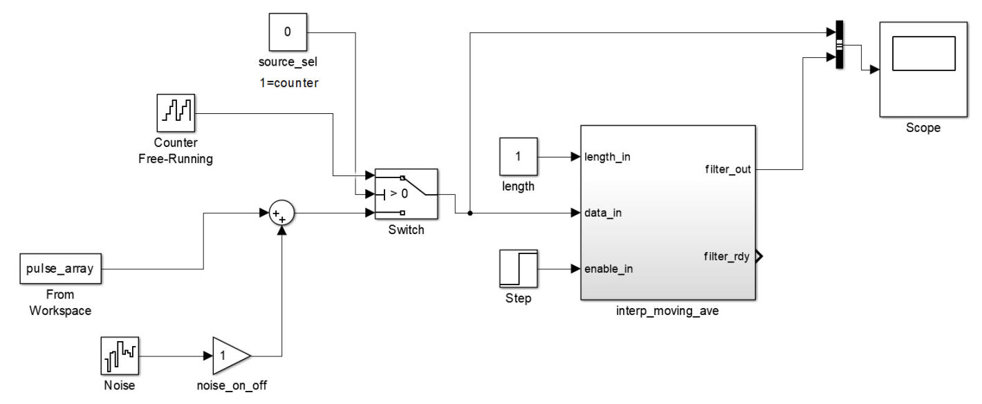
Just as in an RTL design, there will be two parts to the simulation: the part that will be targeted into the FPGA – I’ll call this the model, and the part that will be used to simulation test this – the simulation testbench. Once the design is simulation tested, one approach is to copy over the model and connect it into the same simulation testbench. Then, one can go through the blocks in this copied model and convert them to fixed point, making all of the tradeoffs to deal with the growing precision that occurs. With both fixed and floating point models connected in the same testbench, one can perform the same simulations to gauge the error in converting to fixed point. It also a good practice to create simulations that test the boundary conditions and overflow – something that isn’t a concern in the floating point model, but could wreak havoc on the fixed point world.
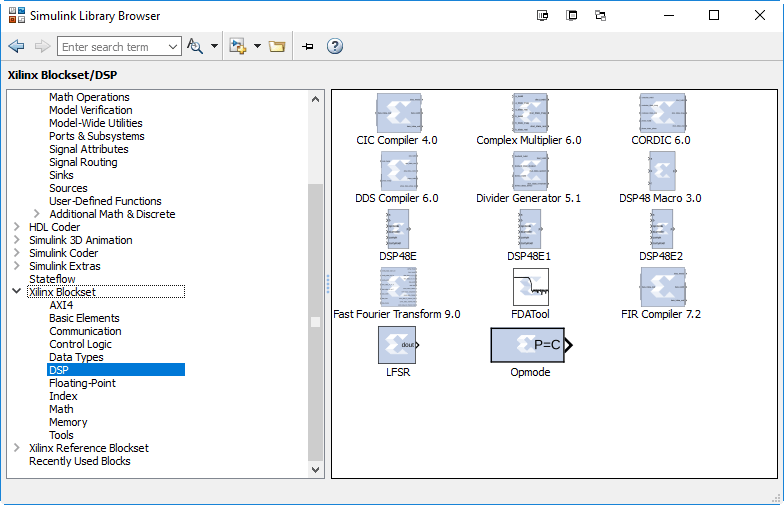
After this step is complete, the next step is to convert the model to the Xilinx blockset. There are just a few rules that need to be followed to capture a design with the Xilinx blockset:

